")


Simply pay attention to the laying direction
Lay all of the boards in the same direction in order to obtain a homogeneous surface effect. This direction is shown by an arrow in the board groove or on a label on the board. Mix the boards prior to laying. This allows the slight differences in the colour of the boards to emphasise the natural appearance.

Mechanical characteristics of the boards and floor panel
| Three-point bending | Boards |
|---|---|
| Support clearance: | 360 mm |
| Test speed: | 20 mm/min |
| Breaking load: | 3.200 N* |


Item overview for assembly on concrete edge stones

Construction beam 40 x 40 mm

Fastening screw for sub-construction 7,5 x 92 mm

Connecting Clamp

Rubber pad 100 x 60 x 20 mm 100 x 60 x 10 mm 100 x 60 x 3 mm

Locking clamp (one-piece) incl. Screws

Edge clamp (two-piece)

Groove bridge

Clip & edge clip incl. screws

M6 x 40 mm Screws in order to screw short deck board sections

Distance Fix for the creation of a heading joint (5 mm/8 mm) incl. Screws

Retaining band, self-adhesive

M8 x 40 mm fastening srews for the Rhombus Profile as a closing strip

M8 x 80 mm Fastening screw for the Rhombus Profile as a closing strip
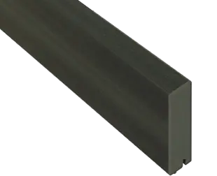
Rhombus profile as a closing strip 81 x 20,5 x 4200 mm

Fokus Chocolate Black
for deck boards Glacier , Terra Trend Terra, Relief R24 Fokus Chocolate Black

Fokus Brown
for deck boards Dolomit Brown and Fokus Brown

Fokus Grey
for deck boards Glacier Graphit, Dolomit Grey and Fokus Grey, Trend Graphit, RELIEF R24 Fokus Grey
Green Black
for deck board Dolomit Green Black
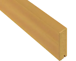
Sandy Brown
for deck board Dolomit Sandy Brown
Easily implemented variable installation heights
Our patented click system allows construction heights of between 98-143 mm (in steps) to be easily implemented.

Preparation of the subsurface
1. Establish a soil formation
Establish a soil formation with a gradient of 4%.
2. Create a ballast bed
Whilst ensuring that it protrudes by 500 mm around the circumference of the terrace, create a ballast bed (including drainage) with a 2% gradient. Apply fine grit to the ballast bed with a gradient of 2%.
Assembly of the ConStep plates
3. ConStep mounting plate
In all of the ConStep mounting plate, click in the single and double mounts to the same height and centrally bond into place with a piece of retaining tape.
4. Distance to the house wall
Position the ConStep panel with double mount at a distance of 80 mm to the house wall and a maximum alignment of 500 mm to the next ConStep panel with double mount.
5. Dimension between axes
Position the ConStep panel with single mount with max. 400 mm dimension between axes in the next row.
6. ConStep double mount
Conclude the end of the deck using a further ConStep double mount. Click the sub-construction into place.
7. Minimise protrusions
Minimise protrusions. In order to do so, turn the ConStep panel where necessary.
8. Reinforce the sub-construction with perforated band
Using the ConStep assembly clip, reinforce the entire sub-construction with perforated band in a crosswise manner.
Assembly of the board with locking clamp
9. Position the edge clamp
Saw into the construction beam from the side from which the boards are to be laid. This must be performed 12 mm from the edge, to a depth of 5 mm and to a width of 2 mm. Position the edge clamp in this groove and, using pliers, fix together with the construction beam and push the board into the edge clamp.
10. Place the locking clamp
Place the locking clamp onto the construction beam, fix into place using pliers and push into the deck board groove. Using the supplied screw, engage the lock lips into every 3rd deck board row on the construction beam.
11. Saw the construction beam to length
After the penultimate board, determine the required width for the last deck board and saw the construction beam to length so that it is flush. In doing so, please note that the construction beam must protrude by 12 mm from the last board (for fixation of the edge clamp).


Assembly with the example of ConStep double mount

Installation using the example of concrete kerbstone

Additional items for assembly with the ConStep system

ConStep mounting plate

ConStep double mount

ConStep single mount

ConStep Rubber pad
300 x 300 x 10 mm
300 x 300 x 5 mm
300 x 300 x 3 mm

Perforated band
