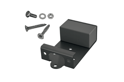
Simple assembly
- Avoid contact between the construction elements.
- Ensure that the subsoil is firm and has a good load bearing capacity. For applications that require an official technical approval, a static sufficiently measured, bearing and walkable foundation as a support for torroTIMBER® boards /subconstructions is also required.
- When using metric screws, all of the holes should be pre-drilled so that the part that is to be fixed in place, is 2 mm larger and the retaining drillhole is exactly 0.5 mm smaller than the diameter of the screw!
- Observe the minimum clearances of the expansion joints so that the construction can expand without force if necessary and a sufficient amount of ventilation from underneath is ensured.
- Cutting the longitudinal side of the boards may result in board offset.
- Do not lash down or brace the deck during construction.
- Rod-shaped components that are to be screwed onto a rigid substructure, always have the fixed point in the centre and floating outwards so that thermal expansion and an expansion due to an absorption of water can be compensated for.
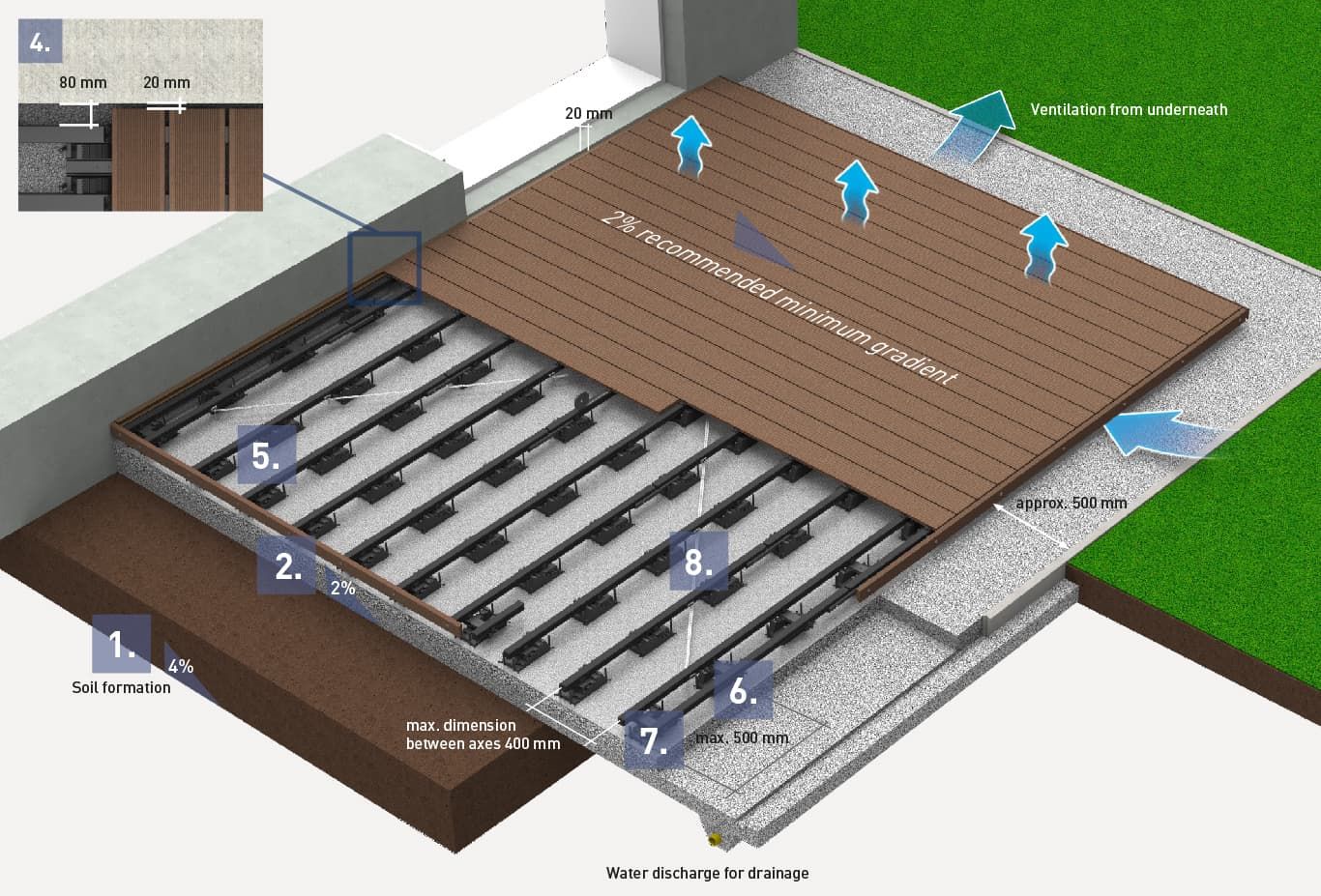
- Distance between the deck board and all fixed components: 20 mm
- Do not fill cavity spaces between the level surface of the gravel and subconstruction elements.
- Recommended minimum gradient of 2 % in the longitudinal direction of the boards.
- Maximum deck board protrusion over the last subconstruction is 50 mm.
- Production-related dimension tolerances regarding length, width and thickness are to be taken into account during assembly and the dimensions on the construction must be examined once again.
- Choose the material versions for punched parts, such as standard steel or stainless steel for clips, to suit your structural conditions.
- The boards are to be cut off at right angles and then to chamfer.
- Wind load must be considered as a lifting load in the construction when designing a terrace.
- Predrill all of the holes before screwing it in place.
Easy processing of
the material.
Simple assembly for all structure types
We want you to enjoy your new terrace for a long time. Only use original torroTIMBER® parts and observe our processing recommendations to ensure that our warranty does not become void. Coordination with the manufacturer must take place and respective approval must be obtained in the event of special structures that deviate from these processing recommendations or the online planner in order for any potential warranty claims to be accepted.
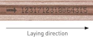
Simply pay attention to the laying direction
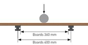
Mechanical characteristics of the boards and floor panel
| Three-point bending | Boards |
|---|---|
| Support clearance: | 360 mm |
| Test speed: | 20 mm/min |
| Breaking load: | 3.200 N* |
OF 400 MM FROM THE SUBSTRUCTURE.
Production-related dimension tolerances of torroTIMBER® boards and floor panel
| Specification | Tolerance field | Dimension | Measurement point | Permitted dimension change after water absorption* guaranteed values |
Remark | ||
|---|---|---|---|---|---|---|---|
| Profile length | 3000 / 4000 / 5000 mm | ±0,0/+10,0mm | Length | Maximum value | Board length 3000 mm Board length 4000 mm Board length 5000 mm |
≤ 9,0 mm ≤ 12,0 mm (≤ 3 mm/m) ≤ 15,0 mm |
Distance from other fixed components, min. 20 mm |
| Profile width | 130/138/145/163/ 193/245mm | –2,0/+1,0mm | Width max. 245 mm | Board, centre | max. ≤ 1,2 mm | ||
| Profile thickness | 16/19/25mm | –1,0/+1,0mm | Thickness max. 19 mm | Board, centre | max. ≤ 0,5 mm |
* In the event of exposure to outdoor weathering and construction executed in accordance with the construction manual
Assembly on concrete edge stones
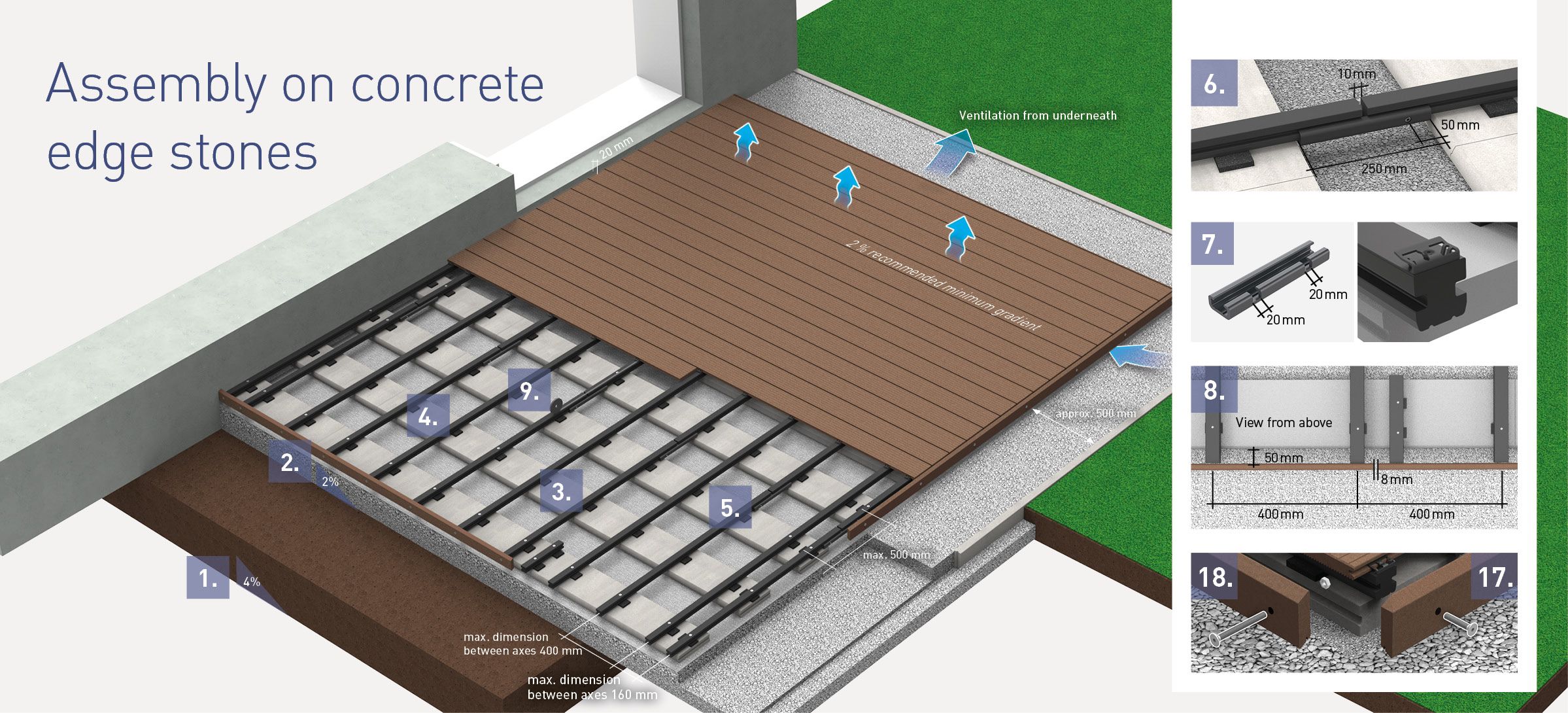
Preparation of the subsurface
Assembly of the subconstruction
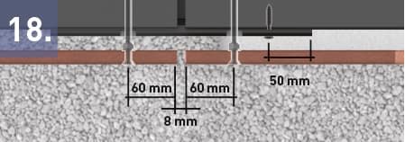
Equally space the construction beams (40 x 40 mm) transversely to the concrete edge stones (the groove is at the bottom), ensuring that there is a protrusion of 50 mm on the end face (see detail 8). Position two beams at the beginning and two at the end (axial dimension: 160 mm). Place 10 mm rubber pads underneath the construction beam and compensate for any gradient differences with additional rubber pads. Screw the construction beams around the entire edge of the terrace and the beams that the retaining band is mounted on, to the concrete slab. When laying the terrace herringbone style, the construction beams need to be screwed to the concrete slabs that are positioned underneath the beginning and end of the board.
If the terrace should be more than 3 m wide, the ends of the construction beam are always to be positioned offset and connected using the connecting clamp. The connecting clamp makes it possible to create terraces that are larger than 12 x 12 m without the requirement for structural expansion joints.
Cut the connecting clamp to 250 mm so that the beam joints are joined to each other and then screw tightly on one side (clearance of the joints: 10 mm).
Saw the connecting clamp to a width of 20 mm and a depth of 10 mm at the outer construction beam so that the rhombus profile can be used as a closing strip in the area of the screwed connection. The butt joint of the rhombus profile accommodate the butt joints of the subconstruction.
Mount an additional piece of construction beam piece (length 320 mm) for butt joints of the rhombus profiles in the direction of the boards. The butt joint of the rhombus profiles will accommodate the butt joint of the boards with the boards laid in herringbone style. Screws are placed in the double mount construction beams.
Fix the retaining band to a construction beam that is located in the centre underneath the board. When using the Distanz Fix when laying herringbone style, the retaining band has to be fixed to each of the construction beams.
Assembly of the boards with clip
Chamfer the cut edges of the boards.
Place an edge clip at the beginning of the face of the construction beam so that it is flush with the beam, pre-drill to a depth of 3 mm and loosely fix in place using a screw (do not tighten yet).
Push the first board onto the positioned edge clip. Use the clip for the following boards, pre-drill to a depth of 3 mm and loosely fix it to the construction beam using the enclosed screws. Now push the next board against it until the clip is positioned against the groove. Tighten the clip applying the average torque after approx. 5 rows of boards have been laid. Repeat this until the last board but one has been layed.
After laying the last board but one, determine the width that is required for the last board and saw the construction beam to the required length so that it is flush. The construction beam has to protrude over the edge of the design beam by 10 mm so that the edge clip can be positioned as a final mounting.
Position the final board and fix the edge clip in place. Pre-drill a hole for the screw and screw in place applying an average torque.
Cut the boards to length at a right-angle at the face edge, ensuring that there is a protrusion on 15 mm. Maximum board protrusion: 50 mm. Chamfer the cut edges.
Mounting the Rhombus Profiles as closing strips
Leave a minimum clearance of 15 mm between the rhombus profile and the surface of the ground.
Screw the rhombus profiles maximum 60 mm from the ends and maximum 400 mm from each other and pre-drill true to the principles. When laying parallel to the boards, screw on using M8 x 40 mm screws so that they are flush with the end edge of the construction beam. Act in accordance with Detail 8 as regards butt joints.
When mounting at the face towards the boards, screw on using M8 x 80 mm fastening screws and use the corresponding nut as a spacer and in order to fix in place.
Item overview for assembly on concrete edge stones
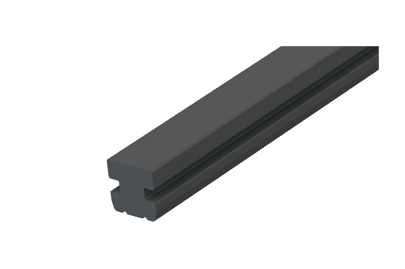
Construction beam 40 x 40 mm
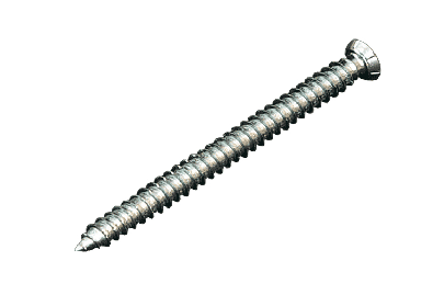
Fastening screw for sub-construction 7,5 x 92 mm
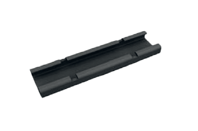
Connecting Clamp
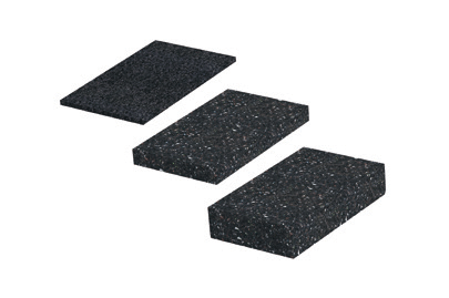
Rubber pad 100 x 60 x 20 mm 100 x 60 x 10 mm 100 x 60 x 3 mm
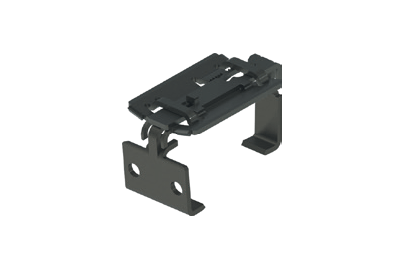
Locking clamp (one-piece) incl. Screws
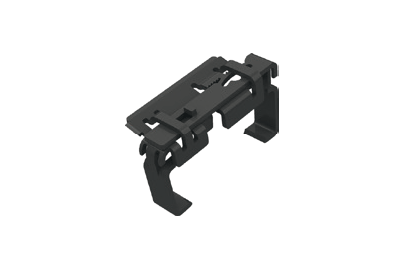
Edge clamp (two-piece)
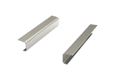
Groove bridge
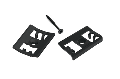
Clip & edge clip incl. screws
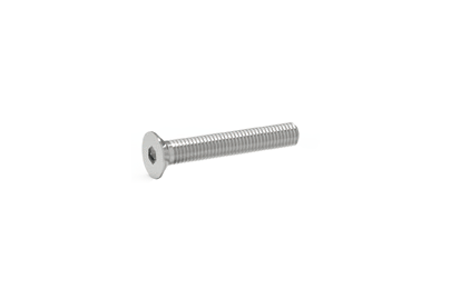
M6 x 40 mm Screws in order to screw short deck board sections
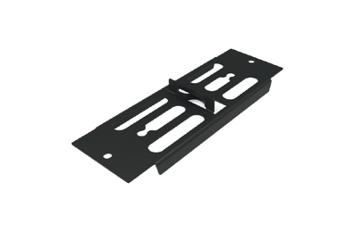
Distance Fix for the creation of a heading joint (5 mm/8 mm) incl. Screws
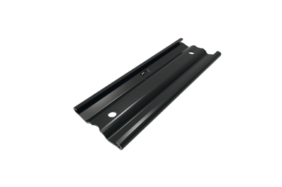
Arretier Fix for the height locking of the butt joints
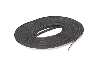
Retaining band, self-adhesive
M8 x 40 mm fastening srews for the Rhombus Profile as a closing strip
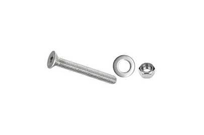
M8 x 80 mm Fastening screw for the Rhombus Profile as a closing strip
Rhombus profile as a closing strip 81 x 20,5 x 4200 mm
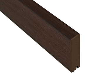
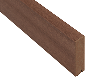
Fokus Chocolate Black for deck boards Glacier Terra, Trend Terra and Dolomit Fokus Chocolate Black
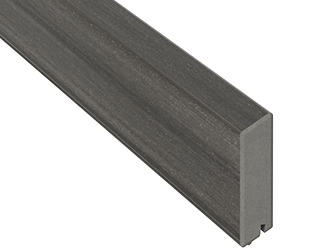
Fokus Brown for deck boards Dolomit Brown and Fokus Brown
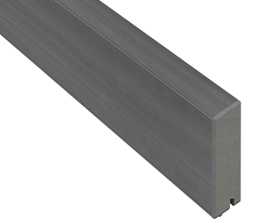
Fokus Grey for deck boards Dolomit Grey and Fokus Grey, Glacier Graphite and Trend Graphite
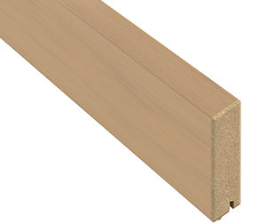
Platin for deck boards Dolomit Platin and Trend Titan
Ecru for deck boards Dolomit Ecru
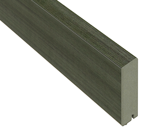
Jade for deck boards Dolomit Jade
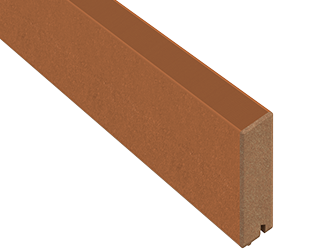
Umbra for deck board Trend Umbra
Assembly with ConStep system
Easily implemented variable installation heights

Preparation of the subsurface
Assembly of the ConStep plates
Assembly of the board with locking clamp

Herringbone pattern installation with double sub-construction beam
Assembly with the example of ConStep double mount
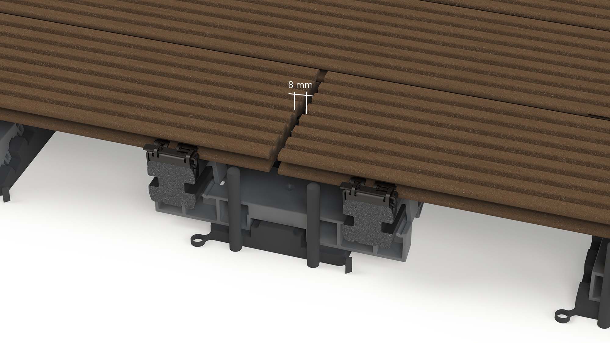
Installation using the example of concrete kerbstone
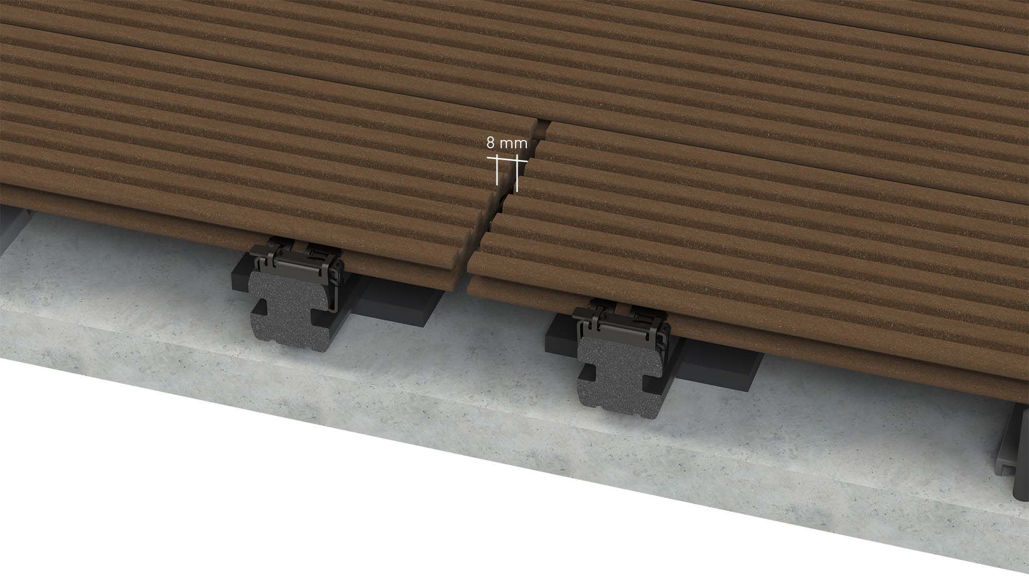
Additional items for assembly with the ConStep system
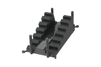
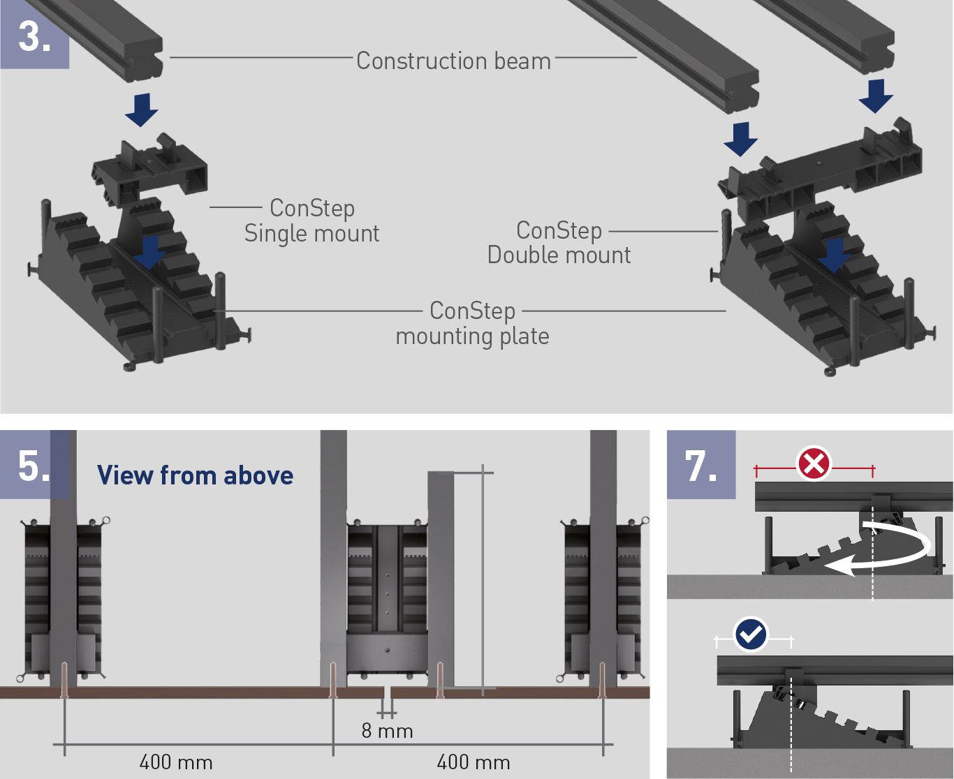
ConStep mounting plate
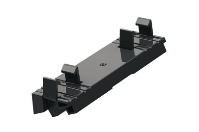
ConStep double mount
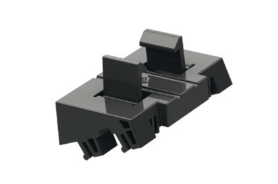
ConStep single mount
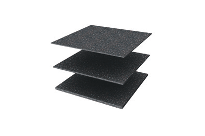
ConStep Rubber pad 300 x 300 x 10 mm 300 x 300 x 5 mm 300 x 300 x 3 mm
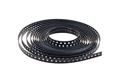
Perforated band
